How to calculate effective Production Sequencing?

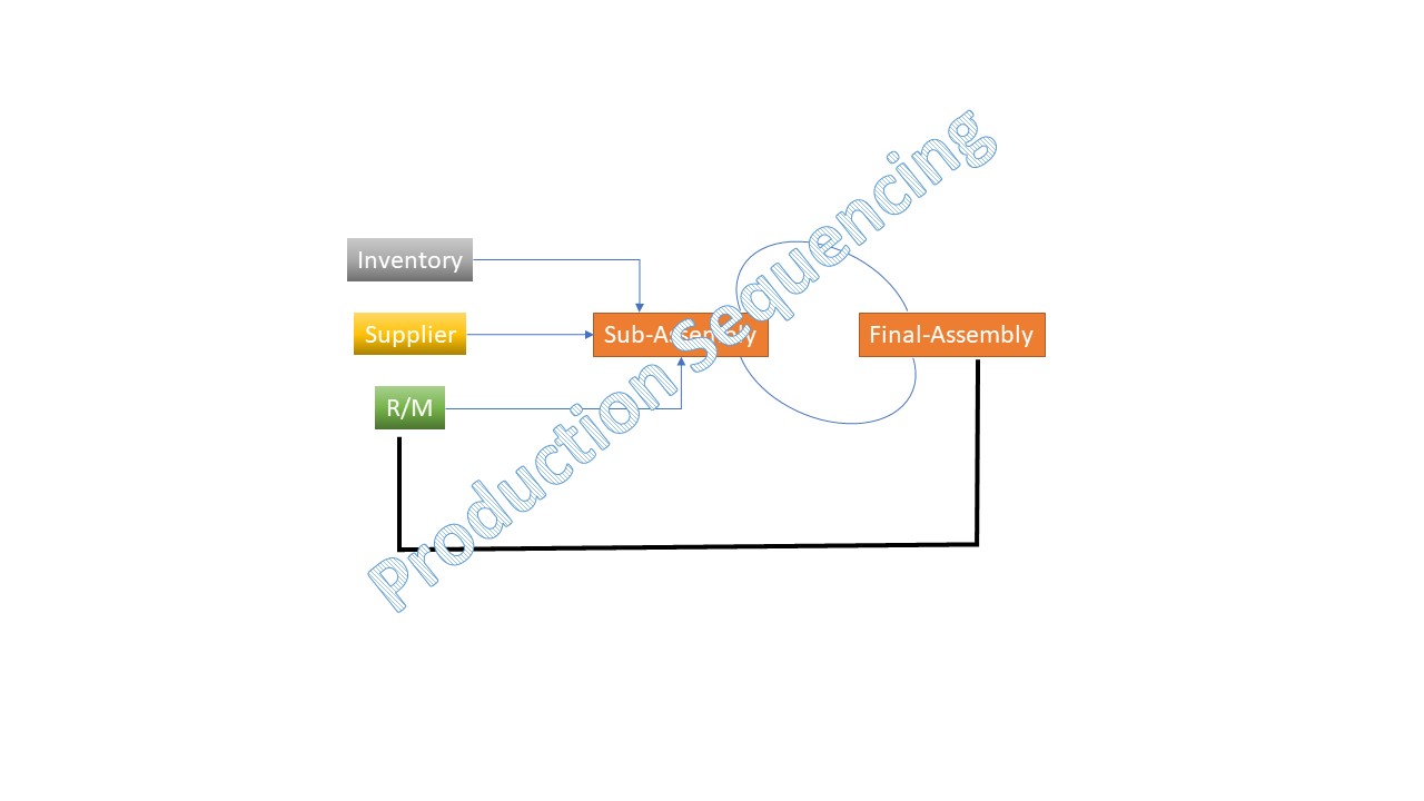
Production Sequencing

How to calculate effective Production Sequencing?

Hi readers! Today we will be discussing on how to calculate effective production sequencing. Production sequencing is the most important part of PPC (Production planning and control). Its helps to meet the on-time customer delivery and enhance customer satisfaction and the Brand name.

Before doing the production sequencing, at least prioritize and consider some factors like processing time, due date, delivery time, flow time minimization, work-in-process inventory minimization, idle time of machines minimization, etc. for effective sequencing. And another important part is the methods of priority for production sequencing like [1] FCFS ( First come first served), [2] SOT ( Shortest operating time), [3] STR (Slack time remaining), [4] EDD (Earliest due date), [5] STROP (Slack time remaining per operation), [6] CR (Critical Ratio), [7] LCFS (Last- come first served).

Understanding of Several Methods:

  • First come first served: Production is run w.r.t first arriving in the department, let’s say the first week of the month the “X” customer has ordered 5nos and 10nos of product-1 and product-2 for supply within the next two weeks. And later the same customer ordered product-3 in the second week of the same month and they need product supply at the end of the second week. Now the important thing is how to apply FCFS methods to select the product sequence means with the product need to be started first for manufacturing. Details of the calculation have discussed below example.
  •  Shortest operating time: Manufacturing the product with the shortest processing time means the shortest completion time.
  • Slack time remaining: Time remaining before the due date remaining completion time.
  • EDD (Earliest due date): Produce the product with the earliest due date first.
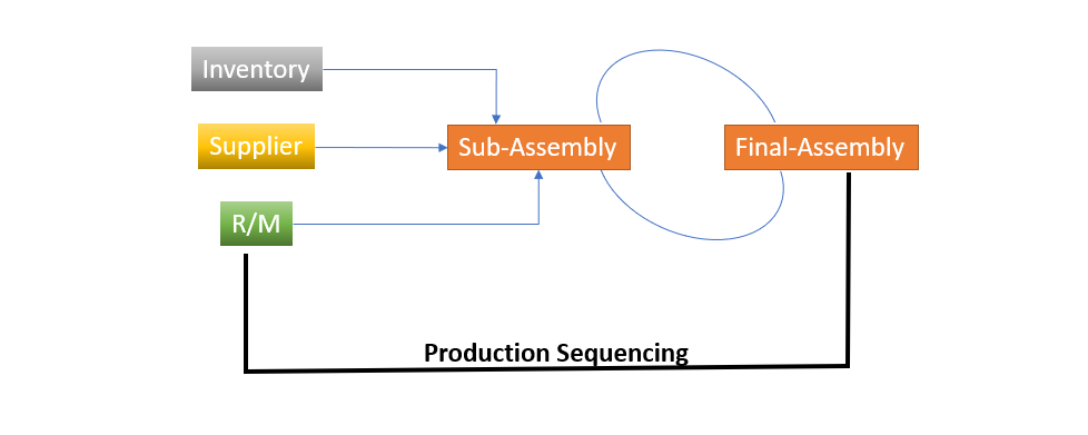
Production Sequencing

Step by step calculation of effective Production Sequencing with manufacturing example:

Here, we are going to calculate the production sequencing with the different scenarios by applying multiple methods.

Manufacturing Example:

Suppose a company namely XYZ Pvt. Ltd has got an order of 6 types of product, details of orders are given below.

Product NameDelivery DaysProcessing Time (Days)
A-Prod64
B-Prod75
C-Prod83
D-Prod97
E-Prod32
F-Prod21

After getting the orders, the production supervisor has applied several methods like [1] FCFS ( First come first served), [2] SOT ( Shortest operating time), [3] STR (Slack time remaining), [4] EDD (Earliest due date), [5] STROP (Slack time remaining per operation), [6] CR (Critical), [7] LCFS (Last- come first served) and selected the effective production sequence among all the methods.

First, he has applied the FCFS (First-Come First Served) Method. All the above products (Prod-1 to Prod-6) are completed in a single machine.

Methods-1 (FCFS):
Product NameProcessing Time (Days)Delivery DaysFlow Time in DaysOn-time or late delivery in days
A-Prod464On-time
B-Prod574+5=9Late=2
C-Prod384+5+3=12Late=4
D-Prod794+5+3+7=19Late=10
E-Prod234+5+3+7+2=21Late=18
F-Prod124+5+3+7+2+1=22Late=20
First come first served Method

According to the FCFS method, the supervisor has calculated the sequence, on-time, and late delivery time in days. As we can see that only A-prod can deliver on time. and the rest 5 products will be late by 2,4,10,18,20 days. On average a job will be late by 9 days.

Method-2-SOT (Shortest operating time):
Product NameDelivery DaysProcessing Time (Days)Flow Time in DaysOn time or late delivery in days
F-Prod211On time
E-Prod321+2=3On time
C-Prod831+2+3=6On time
A-Prod641+2+3+4=10Late=4
B-Prod751+2+3+4+5=15Late=8
D-Prod971+2+3+4+5+7=22Late=13
Shortest operating time Method

The above data indicates that 3 products will be on time. and the rest three products will be late by 4,8 and 13 days. On average, a product will be late by 4.17 days (4+8+13 /5).

Method-3- EDD (Earliest due date):
Product NameDelivery DaysProcessing Time (Days)Flow Time in DaysOn-time or late delivery in days
F-Prod211On-time
E-Prod321+2=3On-time
A-Prod641+2+4=7Late=3days
B-Prod751+2+4+5=12Late=7days
C-Prod831+2+4+5+3=15Late=12days
D-Prod971+2+4+5+3+7=22Late=15days
Earliest due date Method

After applying the method-3, you can see that only 2 products i.e. “F-Prod”, “E-Prod” will be on-time. And rest 4 products will be late. But on an average a product will be late by 6.16days.

Conclusion:

Here, we will compare the above three methods and will find the best among them and accordingly the schedule will be decided.

MethodsFlow Time in Days (total)Average Lateness in daysOn-time delivery(total)
First come first served87 days9 days1 number
Shortest operating time57 days4.17 days3 number
Earliest due date60 days6.16 days2 number

According to the above comparison of three methods, the shortest operating time method result is the best one compared to the other two methods. In this way, you can select the best and most effective production sequencing.

As per the SOT (Shortest operating time) method, First, you have to start production of “F-Prod” and then. need to follow the below sequence as;

Product NameProduction Sequence
F-Prod1st
E-Prod2nd
C-Prod3rd
A-Prod4th
B-Prod5th
D-Prod6th

Free Templates / Formats of QM: we have published some free templates or formats related to Quality Management with manufacturing / industrial practical examples for better understanding and learning. if you have not yet read these free template articles/posts then, you could visit our “Template/Format” section. Thanks for reading…keep visiting techiequality.com
Popular Post:

Turtle Diagram Example | QMS Standard Requirement | Free Template | Format

Turtle Diagram Example

Turtle Diagram Example | QMS Standard Requirement | Free Template |Format:

Hi readers! Today, we will discuss on various types of turtle diagram example of the manufacturing process, incoming inspection process, internal auditing process and pre-dispatch inspection process, etc. and also we have provided the link for the sample template/ format of the turtle diagram in below. Just download the format and customize it according to your process requirements. 

DOWNLOAD– Sample Turtle Diagram Template/format.

Turtle Diagram:

The turtle diagram is a visual tool that is generally used to represent details elements of a process like input, output, method, resources, performance, etc. it helps to improve the process performance. In many industries they are using the turtle diagram for process details and interaction, mapping, etc. so it’s a very useful and popular visual tool.

QMS Standard (ISO 9001 & IATF 16949) Requirement w.r.t Turtle Diagram:

The turtle diagram is not a mandatory requirement of QMS standards like ISO 9001 and IATF 16949, but you can use this diagram to represent the process details like the process’s method, resource requirement, process measurement, process interaction, input and output of the process, etc. To comply the clause-4.4.1 of the QMS standard (ISO 9001 & IATF 16949) requirement, many organizations have implemented the Turtle diagram but there is so many other diagrams also exist that you can use like Matrix, Flow charts, process mapping, SIPOC, etc. but Turtle Diagram is a very useful and easy diagram so that, many organization is being used it.

How to Implement Turtle Diagrams in the Manufacturing Industry? And Nomenclature:

Before discussing of implementation of the Turtle Diagram, we have to illustrate the terms related Turtle Diagram, first. If your organization is certified with QMS standards like ISO 9001 and IATF 16949 Then, you are compulsory to comply with the standard requirement of clause 4.4.1, To do so, you may prepare a turtle diagram but you can represent it in other ways as well. But the Turtle Diagram is a frequently used diagram and very easy to use. So, here we are going to describe it in detail.

As you know that in the wide range the QMS standard asked for process details like Process interaction, Input of process, Output of process, resources, methods, and Process results, etc.

Note, that a Turtle diagram is not a mandatory requirement of the standard to represent the process requirement, but you can prepare it to do so.

Nomenclature of Turtle Diagram:
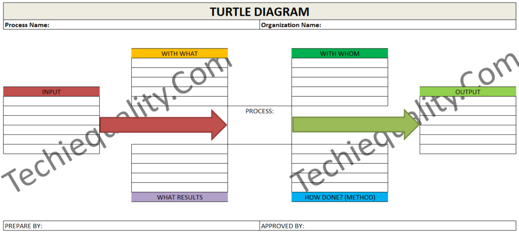
Turtle Diagram Example

In the above Turtle Diagram, we have divided resources into two categories like [1] With Whom [2] With What. Details of Each and every category are mentioned below.

With Whom: It is nothing but its talk about the people (Personnel) involved with the Process.

With What: Resources requirement to execute the process like infrastructure, Machine, instrument, equipment, material, etc.

How Done: Method, Phases how to complete the process in successfully. For example, a list of documents like Procedures, Work instructions, test methods, specifications, drawings, etc.

What Result: Process-related objectives and targets, monitoring and measurement-related results, etc.

Input: Details of process requirement.

Output: Process output.

How to Implement Turtle Diagram in Manufacturing Industry?

Here, I’m going to share my own experience regarding turtle diagram implementation with an industrial example. Two years back, when our organization thought about QMS certification, Our MR has prepared QMS implementation Roadmap and he has given me one important responsibility for preparing the documentation and implementation of ISO/IATF clause 4.4.1 requirement for the Incoming material inspection process and they have imparted training on this subject as well. I think this is the right platform to share my own experience on it so that other can get benefits and they can prepare this diagram, also. But the requirement of ISO/IATF clause 4.4.1 documentation is fulfilled by preparing various docs. But turtle diagram is one of them, but the turtle diagram is not a mandatory requirement of the standard. Anyway, I am going to share how to prepare the turtle diagram for the Incoming material Inspection Process.

Step By Step Process:
  • Understand the process in detail by consulting with the pertinent process owner or head.
  • List out the resource requirements, like trained personnel, inspector, infrastructure, machine, instrument, equipment, lighting facility, details input to execute the process, process method, SOP, other related support, Process results, and finally, the output of this process.
  • After getting all the information, now it’s time to prepare the Turtle Diagram.

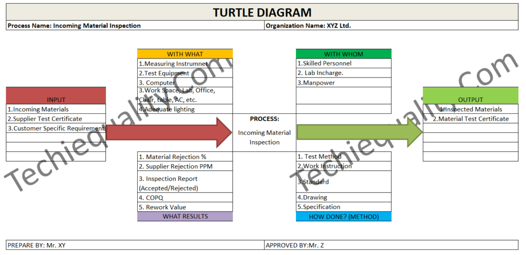
On the same subject (Incoming Material Inspection Process), we have prepared the Turtle Diagram for your easy understanding, just go through it.  

Turtle Diagram Example
Turtle Diagram Example (Incoming Material Inspection Process)

FAQ:

There is a misunderstanding in many organizations that the Turtle diagram is the mandatory requirement of QMS Standard to visualize the process details of each and every element.

But the one-line answer is “NO”, there is no such specific requirement for a turtle diagram. You can represent and fulfill the QMS standard requirement by your own principle as well. But many organizations are being used the Turtle Diagram.

Free Templates / Formats of QM: we have published some free templates or formats related to Quality Management with manufacturing / industrial practical examples for better understanding and learning. if you have not yet read these free template articles/posts then, you could visit our “Template/Format” section. Thanks for reading…keep visiting techiequality.com\

Useful Post:

Correlation analysis in excel |3 best method |step by step guide with example

How to Plot Scatter Diagram in Excel? |Guides with example | Interpretation

Scatter Diagram Template |Industrial Example |Download Excel Format

More on TECHIEQUALITY

Plan Do Check Act Cycle | PDCA Cycle Manufacturing Example | Implementation

Plan Do Check Act Cycle

Plan Do Check Act Cycle | PDCA Cycle Manufacturing Example | Implementation:

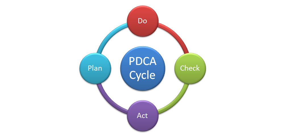
Hi readers! Here, we will discuss the details on PDCA cycle (Plan Do Check Act Cycle) with the Industrial/ Manufacturing example. The PDCA Cycle is the most popular cycle/ method used in industry/ organization for continuous/continual improvement and process improvement and problem solving. The PDCA cycle consists of four phases i.e. [1] Plan, [2] Do, [3] Check, & [4] Act. The Plan-Do-Check-Act Cycle is also called as Deming Cycle/Wheel, PDSA Cycle (Plan-Do-Study-Act), or Plan-Do-Check-Adjust Cycle.  

Plan Do Check Act Cycle / PDCA Cycle / Deming Cycle:

Plan Do Check Act Cycle

Basically, the PDCA (Plan-Do-Check-Act) cycle is used for continual/ continuous improvement. If you find any problem in the production process or would like to improve the production process then you can easily apply this management approach. But you can apply this PDCA cycle to any type of improvement project/ objectives. It is not only used for Process improvement but also used for Problem-solving. The details of individual stages /phases are described in below.

Plan: To develop the Potential solutions.

Do: To execute the Plan.

Check: To Review, verify, inspect, evaluate, analyze the data, and compare the results (Before and after) w.r.t Objectives that the plan/solution is satisfactory or not.

Act: If the solution is satisfactory then implement it. If it is not satisfactory then take the containment action and repeat the Cycle.

How to Implement PDCA Cycle in the Manufacturing Industry for Continuous/ Continual Improvement:

I am so excited to share my own experience. I have implemented so many improvement projects through the PDCA Cycle, but here I am going to share only manufacturing process improvement-related examples.

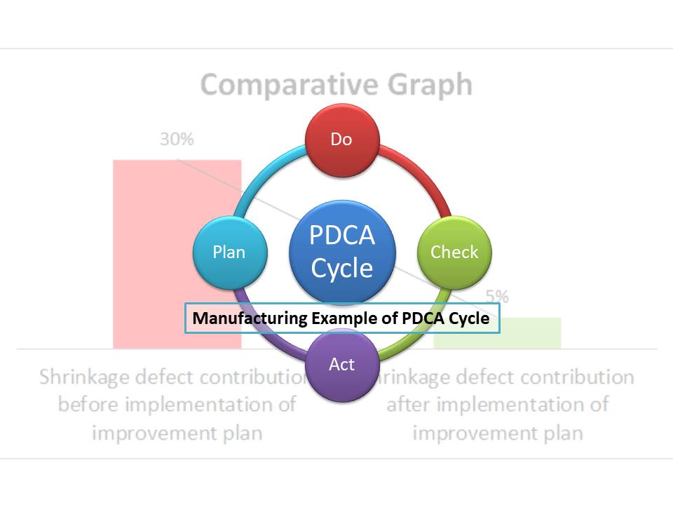
When we had prepared the monthly quality report of the manufacturing process, we got that the shrinkage problem was a vital problem and almost contribute the 30% among the entire problem and on the basis of the report we have decided to improve the process and to reduce at least shrinkage defect from 30% to 5%. Accordingly, objective has been taken and followed the PDCA cycle to resolve it and to improve the manufacturing process.

PLAN:

Before applying the method, we have formed a Team and described the problem, took the objective, and prepared the plan, which is described as below.

Step-by-step method that we have followed to prepare the Plan:

1] To Form a Team.

2] To Take an Objective.

3] To Prepare the Roadmap /Activities flow chart.

Team Formation:
Name of Project Leader: Mr. S
Name of Team members:
Mr. G
Mr. P
Mr. N

Note: During the team formation, you may consider the members from different and different sections, that are directly associated with your process activity. Because you can easily manage your activities.

Now, the next step is to take an Objective.

Objective: To reduce the Shrinkage defect contribution from 30% to 5% within 3 months.

According to the above objective we have prepared the Plan. And details of the plan are described below.

ActivitiesResponsibilityTime-Line
Data CollectionMr. GWithin 7 days from the starting date of assignment.
Cause and Effect diagram PreparationMr. G & Mr. P(Within 9 days from the starting date of assignment)
Identify the significant causesMr. G & Mr. PWithin 15 days from the starting date of assignment.
Why-Why AnalysisMr. G, Mr. P & Mr. NWithin 20 days from the starting date of assignment.
Identify the Root CauseMr. G, Mr. P & Mr. NWithin 21 days from the starting date of assignment.
Corrective Action planMr. G, Mr. P & Mr. NWithin 25 days from the starting date of assignment.
Preventive Action planMr. G, Mr. P & Mr. NWithin 25 days from the starting date of assignment.
Trial implementationMr. G, Mr. P, Mr. N & Mr. SWithin 75 days from the starting date of assignment.
Comparative study w.r.t ObjectivesMr. G, Mr. P, Mr. N & Mr. SWithin 90 days from the starting date of assignment.
[Table-A, Activities Plan Flow, Plan do check act example /PDCA Example]

 Note: The above activities may change according to the nature of the improvement project. Or whatever objective you have taken. The Aforesaid plan template is only for your reference.

In this way, you may prepare the Plan. Now, we have to move on to the next phase of the PDCA Cycle i.e. “DO”

DO:

In the “DO” phase, you are supposed to implement the Plan that you have prepared in Plan phase. As you can see that we have already prepared the Activity plan and represented in Table-A, and the same implemented.

According to the management approval, we have manufactured the 5-samples as trial implementation. And next activity was done in the “Check” phase.

CHECK:

After trial implementation, whatever data we have collected, just we analyzed all the things, did the gap analysis and we compared the results w.r.t Objectives. And recorded the significant points & collected the feedback as well.

As you know that this phase is important so you have to study and analyze all the things. Similarly, we have compared the results w.r.t Objectives and found the below result.

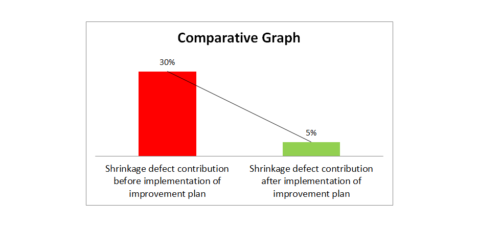
Before Data (old methods/ before implementation of improvement plan)

Shrinkage defect contribution = 30%.

After Data (New methods/ after implementation of improvement plan)

Shrinkage defect contribution = 5%.

Plan Do Check Act Cycle

Conclusion: We have found that the improvement plan is effective and satisfactory.

We have achieved the Objective’s target value. So we have informed to top management about the action plan results to act on it.

ACT:

In the above example, we have found that the solution/improvement plan is satisfactory. So we have finally implemented the new action plan and standardized it. 

If applicable then do the horizontal deployment also.

FAQ:
What do you need to do if your objective will not be achieved?

Ans.: In the “Check” phase when you will find that your objective is not achieved, then you have to take the containment action and you have to repeat the PDCA cycle until resolve the problem or improve the process.

What does PDCA stand for?

Ans.: The full form of PDCA is Plan-Do-Check-Act, and also it is called as Plan do study act, plan do check adjust, Deming Cycle, and Shewhart Cycle.

How does PDCA Improve Quality?

Ans.: Go through the above manufacturing example (Shrinkage Issue), step by Step-by-step phases are mentioned there.

How do you use the PDCA cycle?

Ans.: As you know the PDCA cycle is generally used for continuous /continual improvement. To do so, you have to follow the cycle principles.

1] To form a team

2] To take an objectives

3] To prepare the roadmap/ activities plan

4] Step by step implement the plan.

5] Study the data and compare the results with respect to the objective.

6] Implement the solution (Final implementation); if the result is coming satisfactory otherwise take a containment action and repeat the PDCA cycle again until achieve the Objective’s target value.

Free Templates / Formats of QM: we have published some free templates or formats related to Quality Management with manufacturing / industrial practical examples for better understanding and learning. if you have not yet read these free template articles/posts then, you could visit our “Template/Format” section. Thanks for reading…keep visiting techiequality.com
Useful Post:

Types of Productivity with Example |Productivity Formula |Calculation

How to Calculate Correlation Coefficient (r) |Correlation Coefficient Formula

Correlation Analysis Example and Interpretation of Result

Correlation Analysis in Minitab |Step by step guide with example

More on TECHIEQUALITY

What is Preventive Maintenance? | Predictive Maintenance |Types & Example

What is Preventive Maintenance

What is Preventive Maintenance? | Predictive Maintenance |Types & Example:

Hi readers! Here, we are going to describe the concept of maintenance, types, examples, etc., basically, in this article, we will give more focus on what is preventive maintenance. Predictive maintenance and manufacturing examples and also on how to start a different type of maintenance activities in manufacturing industries. In manufacturing industries, we know very well how important the machine/ equipment’s condition get optimum productivity. Machines are subject to deterioration due to their use and exposure to environmental conditions. So, to maintain the machine condition we may need to carry out the maintenance of machines and equipment. The main purposes of maintenance are;

  • To keep the operation in an optimum working condition.
  • To increase the up-time of the machine.
  • Less expenditure on repairs.
  • To reduce the break-down percentage.
  • To reduce the MTTR Value and increase the MTBF value.
  • Lesser overtime pay for maintenance personnel.
  • Increases productivity and minimizes waste and increases the rate of quality.
  • To meet the time schedule of product delivery to customers.
  • Reduces the downtime of the machines.
  • To reduce the cost of downtime, it means when your machine’s downtime will be reduced then the idle time of the machine, workers, etc. will remain reduced and the respective cost as well. And others cost shall be reduced like scrap cost, rework cost, repair cost, maintenance labour, and overhead cost, etc.  
  • To prolong the useful life of the machine and equipment.
  • To provide a condition of the machine that would permit their operation in the manner required for the process and without interruption to plans involving their use.

Maintenance:

We have already mentioned above the benefits of maintenance that why it is important in manufacturing industries, but anyway it is classified into many types based on different and different factors/ rules /operations, etc.  Like [1] Mechanical maintenance, [2] Utility maintenance, [3] Electrical maintenance, [4] Machine maintenance, [5] Tool maintenance, etc.  And similarly, it is also classified into different types like Preventive maintenance, Predictive maintenance, Breakdown Maintenance, Capital replacement, Planned maintenance, Schedule maintenance, and Corrective maintenance. Etc.

What is Preventive Maintenance

What is Preventive Maintenance?

Preventive maintenance is routine / time-based maintenance where actions are taken in a planned manner to prevent the breakdown of the machine. The main aim is to find out the problem and to fix it before it creates an issue. Generally, in industries, the common popular types of maintenance are used as [1] Preventive and, [2] Predictive maintenance. And also some industries followed and implemented the TPM activities.  

Advantages of PM (Preventive Maintenance):
  • Prolongs asset lifespans.
  • Increased productivity and production.
  • Greater safety of the workforce.
  • Reduces the breakdown and increases the MTBF time.
  • Reduce the scraps, rejection, and rework of products.
  • Lower repair and maintenance costs, etc.
How to start or deploy Preventive Maintenance in Manufacturing Industries?

I am going to share my own experience here, whatever I have learned from a decade of time. Both preventive and predictive maintenance is a useful activity in manufacturing industries. So, if you would like to start Preventive maintenance in your organization then, just follow the below steps.

Step-1:

Go through the past data of breakdown process-wise / area-wise, then workstation-wise, and finally machine-wise. And also carefully read the machine manual, drawing, and related documents to understand the machine function, lubrication system, hydraulic system, etc.

Step-2:

Prepare the fishbone/cause & effect / Ishikawa Diagram of all failures.

Step-3:

Prepare the Standard Operating Procedure.

Step-4:

Prepare the Preventive maintenance check sheet / Checklist.

Step-5:

Prepare the activity road map including the responsibility for each and every activity, plan, and schedule.

Step-6:

Implement the road map, SOP, plan, schedule, and do checking w.r.t check sheet/checklist.

Step-7:

Analyze the data and take the action.

Step-8:

Review and update the documents like SOP, and check-sheet.

Step-9:

If applicable, do the horizontal deployment.

Example:

We have decided to start the Preventive maintenance of Process-1, Process-2, and Process-3, So accordingly both plan and schedule have been prepared.

Preventive Maintenance Plan of Process-1, having total 4 machines, M1, M2, M3 & M4.

MonthWeek-1Week-2Week-3Week-4
Jan.M1M2M4M3
Feb.M3M1M2M4
Mar.M3M4M1M2
Apr.M4M3M2M1
May.M3M2M1M4
Jun.M2M1M4M3
Jul.M1M2M3M4
Aug.M4M1M2M3
Sep.M3M4M1M2
Oct.M4M3M2M1
Nov.M3M2M1M4
Dec.M2M1M4M3
Annual PM Plan

After consultation with the production department and considering machine availability Sr. Maintenance Engineer has prepared the Preventive maintenance schedule and carried it out accordingly.

PM Schedule for the Month of Jan’yyyy.

M/CWeek-1Week-2Week-3Week-4
M1-Plan4.4.yy /Sunday
Actual
M2-Plan11.4.yy/Sunday
Actual
M4-Plan18.4.yy/Sunday
Actual
M3-Plan24.4.yy/Saturday
Actual
Monthly PM Schedule
What is Predictive Maintenance?

Predictive maintenance is condition-based maintenance that monitors the condition & performance of equipment to reduce the probability of failure.

Advantages of Predictive Maintenance:
  • Improve asset reliability.
  • Provide better product quality.
  • Improve the condition of equipment, etc.
The basic requirements for good maintenance practices:

The following are the basic requirements for achieving good maintenance practices as;

  • Good supervision of the maintenance department.
  • Do the maintenance plan and schedule a consultation with the production department, electrical department, utility service department, etc., and prioritize the machine to be covered under maintenance.
  • Maintenance personnel should be well-trained.
  • SOP, standard, to be followed.
  • Adequate stock of spares should be kept.
  • A checklist, logbook, and maintenance register should be maintained.
  • 5’S to be maintained.
  • CLIT to be followed.

Free Templates / Formats of QM: we have published some free templates or formats related to Quality Management with manufacturing / industrial practical examples for better understanding and learning. if you have not yet read these free template articles/posts then, you could visit our “Template/Format” section. Thanks for reading…keep visiting techiequality.com
Useful Post:

Simple Moving Average Formula |Calculation |Excel Template |Example

MTBF and MTTR |Template |Format |Calculation | Manufacturing Example

AIAG VDA FMEA Key Changes | Overview | 7 Step FMEA |PFMEA |1st Edition 2019 | Training

5G Problem solving technique | Manufacturing Example |Free Template

More on TECHIEQUALITY

Types of Productivity with Example |Productivity Formula |Calculation

Types of Productivity with Example

Types of Productivity with Example |Productivity Formula |Calculation

Hi readers! Today we will discuss on types of productivity with example. Productivity is an economic measure of the effective use of resources. It means how much output is obtained w.r.t effective usages of input in a given time period.

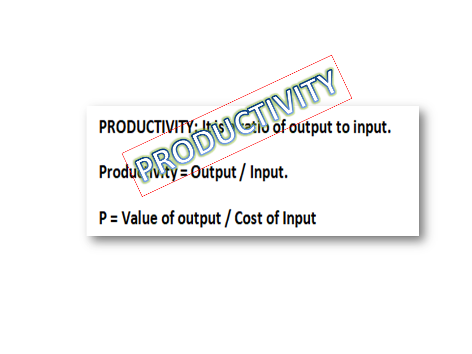
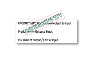
PRODUCTIVITY: It is a ratio of output to input.

Productivity = Output / Input.

P = Value of output / Cost of Input

Types of Productivity with Example

The units of output and input may vary from industry to industry. But some common units of outputs are KWH, Units, Tonnes, MT, litres, KG, and similarly, an input could be time, cost, etc. Inputs are resources such as labour, energy, materials etc. used to produce the output such as goods or services. And also, the output may be measured per shift, per week, per month or per hour.

Types of Productivity with Example:

Productivity is generally classified into three types as [1] Partial Productivity, [2] Multifactor Productivity, [3] Total Productivity. 

Partial Productivity = Output / Single Input.

For example, a company produced 2000 pieces of finished product per day involving 2 labours per shift. Here we would like to calculate the labour productivity.

Labour productivity = 2000 / (6*8)

= 2000 / 48

= 41.66 pieces per hour.

Other common terms used to calculate the partial productivity industry are Machine productivity, capital productivity, Material Productivity, etc.

Multifactor Productivity = Output / more than one Input.

For example, a company produces 2000 pieces of finished product per day with input like labour cost $200, Machine cost $300, and material cost of $500. What is the multifactor productivity?

Multifactor Productivity = 2000 pieces / ($200+$300+$500)

= 2000 pieces/ $1000

= 2 Pieces per dollar.

Total Productivity = Output / All Input.

For calculating the total productivity you have to consider the values of output in rupees and cost of all inputs in rupees.

Note that productivity is generally calculated to know the performance, effectiveness, and etc. but the challenging thing is how to improve productivity. For doing so either you have to increase the output or decrease the input.

Useful Post:

Pull Production System | Concept.

Toyota Production System Tools & Technique

Free Templates / Formats of QM: we have published some free templates or formats related to Quality Management with manufacturing / industrial practical examples for better understanding and learning. if you have not yet read these free template articles/posts then, you could visit our “Template/Format” section. Thanks for reading…keep visiting techiequality.com
Popular Post   

5G Problem solving technique | Manufacturing Example |Free Template

5G Problem solving technique

5G Problem solving technique | Manufacturing Example |Free Template

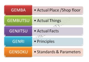
5G Problem solving technique is the most popular Japanese technique, this will help and guide you on how to solve problems. Many problems is being occurred day to day in manufacturing industries like machine breakdowns, customer complaints, in-process rejection problems, material problems, etc.  So to tackle the everyday problem in an unsystematic way is a big challenging work. To overcome this issue, you can follow the 5S Japanese concept to resolve actual/real place problems. It’s namely called 5G because every Japanese word starts with the letter “G” i.e. [1] GEMBA, [2] GEMBUTSU, [3] GENJITSU, [4] GENRI, [5] GENSOKU; these are the 5G where you have to find out the causes. In some cases, you can propose and predict the right cause without visiting the real place and analyzing the actual facts. So this method helps you to resolve the problem.

DOWNLOAD Template- 5W1H, CAPA, 5W2H, 4M check sheet, 8D Format.

5G Problem solving Technique with Manufacturing Example:

Here I’m sharing my own experience that once upon a time I had made a great mistake during an analysis of a customer complaint, one of our customers informed us 5% of the last batch of consignment products had been rejected due to a pinhole issue. Immediately after receiving the customer complaint, we called a meeting with all my team members. And we all started discussing in the conference room to find out the cause of the problem and finally, we proposed an action plan and implemented the same but later on we faced the same problem again.

Our hypothesis / predicted root cause of the failure was invalid. From this experience, I learned that we can’t find an effective action plan by hypothesis or prediction. We must investigate the actual things and verify the principles. And finally, we applied the Japanese technique 5G for problem-solving i.e. [1] GEMBA, [2] GEMBUTSU, [3] GENJITSU, [4] GENRI, [5] GENSOKU.

5G Problem solving technique
Before continuing with the above example I would like to elaborate on the 5G Technique /Method.

GEMBA: Go to the Real /Actual Place.

It’s the place/location where the problem actually occurred e.g. Shop floor. First of all, we have to visit the shop floor or the actual location where we need to start the investigation.

GEMBUTSU: Examine the objects /machine/tools etc.

Your problem-solving team members should examine the machine, parts, objects, and tools that were involved in the failure. During the examination, you can find any clues of failure.

GENJITSU: Check the real Facts

Your team must collect the before and after data and test report, and the team should link the data to the actual facts that what really happened.

GENRI: Refer to the theory /verify the principle.

The team should verify the principle and condition of the machine/equipment/tools etc.

 GENSOKU: Check the process parameters /SOP/Standards.

In this technique the team member should check and verify the process parameters, SOP, Work procedure, Visual instruction, and one-point lesson are followed by operators and that there is no any deviation.

How to apply 5G technique in the manufacturing industry?

We will elaborate on this section continuing with the above example that our action plan against the customer complaint (Pin-hole problem) was not valid. When we applied the 5G technique, the action plan was very effective. First of all, all the team members visited to the shop floor to know the exact problem when we examined the problem we came to know that the actual problem was a blow-hole but not a pin-hole. This was visualized when we went through the G-2 (Gembutsu).

Next, we continued the rest of three-G, some clues we found at the stage of Genjutsu from the Core curing time and some from Gensoku. That curing procedure was not being maintained as per the standard operating procedure. And finally, we concluded after completing the 5G technique on a fact basis that the core curing process was not maintained as per SOP. This is my own experience that how I could able to find out the problem causes using the 5G technique. Given below are the 5-steps, details meanings, concepts, and illustrations of 5G.

Step-by-Step Guide to 5G Problem Solving Technique Application
Step-1GEMBAGo to the real placeCreate a team and visit to the shop floor or a place where the problem occurred
Step-2GEMBUTSUExamine the objectsExamine the machine /tools /equipment/non-conforming pats to know the clues
Step-3GENJITSUCheck the real factsCollect the data and analyze it. And also do the countermeasure.
Step-4GENRIVerify the principleVerify the current practices and condition of m/c, equipment, tools, etc.
Step-5GENSOKUCheck the standardsTo check the process characteristics, SOP, and work procedure, whether it is being followed or not.

Free Templates / Formats of QM: we have published some free templates or formats related to Quality Management with manufacturing / industrial practical examples for better understanding and learning. if you have not yet read these free template articles/posts then, you could visit our “Template/Format” section. Thanks for reading…keep visiting techiequality.com
More on TECHIEQUALITY

Popular Post

AIAG VDA FMEA Key Changes | Overview | 7 Step FMEA |PFMEA |1st Edition 2019 | Training

AIAG VDA FMEA

AIAG VDA FMEA Key Changes | Overview | 7 Step FMEA |PFMEA |1st Edition 2019 | Training

The AIAG VDA FMEA 1st edition handbook has been released first time jointly by AIAG (Automotive Industry Action Group) & VDA (Verband der Automobilindustrie) in 2019. Basically, FMEA is a core tool that is used to identify the potential failure modes of process and product & their cause and effects. Mainly FMEA is three types i.e. [1] PFMEA (Process failure mode and effect analysis), [2] DFMEA (Design failure mode and effect analysis), [3] MSR-FMEA. In this post, we will cover the PFMEA with a manufacturing example.

DOWNLOAD-PDF files of AIAG-VDA FMEA key changes.

If your organization is manufacturing Automotive /Automobile parts/items/products or IATF 16949 certified companies then, you are compulsory to identify the process/ product /design related failures /risks in the FMEA worksheet. It means you have to prepare and implement the FMEA in your organization as a live document. If a customer mentions in their CSR (Customer Specific Requirement) for FMEA requirement then, it’s mandatory for their supplier to fulfil the FMEA requirement, but it does not matter whether your organization is IATF-16949 certified or not. So it’s more important to understand the complete requirements of FMEA before its application in industries. In standard IATF-16949, the application of FMEA is clearly mentioned in several clauses. Now we are going to explain each and every clause of IATF-16949 those are relevant to the FMEA application.

What are the requirements of IATF 16949 for FMEA application?

There are almost 12 sub-clauses in the IATF-16949 standard, where the application and implementation of FMEA are widely explained in the IATF standard. These clauses’s requirements as explained below;

IATF-16949 Clauses /Sub-clauses No: 4.4.1.2: Special approval of PFMEA and DFMEA is required.

8.3.2.1 (IATF Sub-clause): During product development, the organization shall develop the DFMEA and require reviewing the product design risk to reduce the potential risks.

8.3.3.3 (IATF Sub-clause): Special characteristics like fit & function, Critical characteristics, significant characteristics, safety characteristics, etc. are need to be included in the FMEA worksheet.  

8.3.5.1 (IATF Sub-clause): This sub-clause talks about the design risk analysis. DFMEA is the mandatory requirement for design and development output.

8.3.5.2 (IATF Sub-clause): Manufacturing process-related risks need to be addressed in PFMEA.

8.5.6.1.1 (IATF Sub-clause): Process-related risks need to be addressed in PFMEA due to temporary changes in process controls. If your organization has temporarily changed the existing process controls and using the alternative new control method then, the organization shall include the risks of new process control methods in the PFMEA worksheet.

8.7.1.4 (IATF Sub-clause): The organization shall identify the risks related to the product rework process in FMEA.

8.7.1.5 (IATF Sub-clause): The organization shall identify the risks related to the product repair process in FMEA.

9.1.1.1 (IATF Sub-clause): This clause is about the Implementation of PFMEA.              

9.3.2.1 (IATF Sub-clause): Field failure /warranty failure-related risk needs to be addressed in FMEA.

10.2.3 (IATF Sub-clause): As and when problems arise in the process, accordingly review and updation of PFMEA are required.

10.2.4 (IATF Sub-clause): Error proofing details methodology needs to be addressed in PFMEA.

Key Changes of AIAG-VDA PFMEA, 1st edition 2019:
4th edition FMEA (Old version manual)AIAG-VDA FMEA (New version handbook)
RPN (Risk priority number) = S x O x DAction Priority (AP) Table.
Old Severity, Occurrence & Detection RatingsRevised Severity, Occurrence & Detection Ratings
Old worksheet (Format/ Template)Revised worksheet (Format/ Template)
PFD was not an integral partThe Process flow diagram is an integral part of the new manual
Recommended actionPrevention & detection action
ClassificationSpecial Characteristics
 4M-Men, Machine, Material, and Method approach
AIAG VDA FMEA
AIAG VDA FMEA

The complete PFMEA worksheet has made considering 7 Steps FMEA approach, i.e. [1] Planning & Preparation, [2] Structure Analysis, [3] Function Analysis, [4] Failure Analysis, [5] Risk Analysis, [6] Optimization and [7] Risk Communication.

7 Steps FMEA approach
7 Steps PFMEA Approach:
Planning & Preparation:

This is the first step of the FMEA 7-step approach, A Cross-functional team needs to be formed and their roles and responsibilities need to be assigned. In the worksheet, you have to mention those things like Company name, location, PFMEA ID, Confidential Level, etc.

Structure Analysis:

In SA, You have to identify the Process steps i.e. PFD, here you have to identify mainly three things, Process Item, step, and work element (4M).

Function Analysis:

You have to describe the function process item in the next plant process, end-user, and customer, and Simultaneously Process and product characteristics need to be identified.

Failure Analysis:

Here you have to identify the failure effect, mode, and cause.

Risk Analysis:

Current prevention & detection control, AP, SC, etc. need to be addressed.

Optimization:

According to the Level of AP (Action Priority), if required to take the action then, you have to complete the optimization step and again you have to level the PFMEA-AP.

In the previous version, there is a calculation of RPN, but in the new FMEA there is no calculation, just you have to identify the level from the Action Priority Table. Priority High AP level means you must be required to identify appropriate action, Medium priority AP level means you should identify appropriate actions and finally Low priority level (L) means you could identify actions to improve prevention or detection controls.

Result Documentation / Risk Communication:

Now, you have to keep the documents like result communication, CFT meeting report, etc.

7 Steps to Implement the New AIAG-VDA PFMEA in Industry?

In each and every post our authors are trying to share their experience with industrial examples so that the common man can easily understand, learn, and implement it in their workplace. Also, we are always trying to enhance the skill base knowledge of our readers. Anyway, go through the below steps to implement the new PFMEA manual.

Step-1:

To form a CFT team, for example, members should be from different functions like Production, Maintenance, Process quality, product quality, R&D function, etc.

Step-2:

Use the process flow diagram to identify each step of all processes.

Step-3:

Visit the workplace and understand the operational function of each and every step of the process and 4M factors.

Step-4:

Brainstorm the potential failure mode and its effects. accumulate the previous failures from any resources like from shop floor supervisors, operators, from old data, failure due to 4M factors (Man, Machine, Material, Method, etc), and list up the potential effect of failures as well.

Step-5:

To rank the Severity, occurrence, and detection and accordingly choose the level of Action Priority from the AP table.

Step-6:

To address the Current control mechanism in the worksheet.

Step-7:

Take action as per AP level and after implementation of the Action Plan, you have to re-level the PFMEA action priority.

FAQ:

Q1: Shall I need to convert our Approved old PFMEA worksheet to the new one?

A1: Actually it depends upon your customer’s needs and what they want, they need to keep the old approved copy or need the re-approved copy as per the new manual. If your customer asks for a new worksheet as per the 1st edition of AIAG-VDA PFMEA then only you need to change the old one.

Example:

Let’s take an example related to field failure, there is a leakage issue found in the sump chamber, and the same issue was communicated by customers to their supplier to submit the CAPA and updated FMEA. when the supplier investigated the defective product, they found leakage caused due to sand inclusion in the sump base wall. Basically, here, we will focus on how to identify the action priority level of a failure mode. Let you have selected the Severity of FE (Failure effects), Occurrence of FC (Failure cause), and Detection of FC/FM as 9, 2, 1

EffectSPrediction of failure cause occurringOAbility to detectDAction Priority (AP)
Product or Plant effect very high9-10Low2-3Low-Very low7-10H
Product or Plant effect very high9-10Low2-3Moderate5-6M
Product or Plant effect very high9-10Low2-3High2-4L
Product or Plant effect very high9-10Low2-3Very High1L
Action Priority Table (AP)

In the above example, the rating of Severity (S) is 9, Occurrence (O) is 2, and Detection (D) is 1. So now, we will match the value in the AP table to find out the AP level. Go through the below picture to know the AP level.

NEW AIAG VDA FMEA AP TABLE EXAMPLE
action priority table
NEW AIAG VDA FMEA AP TABLE

Free Templates / Formats of QM: we have published some free templates or formats related to Quality Management with manufacturing / industrial practical examples for better understanding and learning. if you have not yet read these free template articles/posts then, you could visit our “Template/Format” section. Thanks for reading…keep visiting techiequality.com
Useful Post:

3MU Check sheet | Details of MURA, MURI & MUDA|Download

4M Checklist Template |Free Download Format

How to enhance production in manufacturing unit?

Fault tree analysis template | Download format free…

More on TECHIEQUALITY

Simple Moving Average Formula | Calculation | Excel Template | Example

Simple Moving Average Formula

Simple Moving Average Formula | Calculation | Excel Template | Example:

A simple moving average (SMA) is a method to get an overall idea about the forecast value of future prediction. If you are planning for Sales, Manpower planning, Production planning, marketing, etc. then SMA will be helping you to forecast future planning. So easily you can do future plans in your business area with the help of expected value based on past demands. In this article, we will be covering the simple moving average formula, calculation, and type of errors with examples. Also, we shall describe how to calculate MA (moving average) with the help of an excel sheet (Data analysis method and function Method).

DOWNLOAD-Sample Example of Moving Average Excel Template.

Simple Moving Average Formula (SMA):

If you would like to calculate the forecast for the coming period based on the Simple Moving Average Method, then formula {F (t, n)} will be the sum of Actual Occurrences or Demands in the past period up to “n” periods divided by the number of periods to be averaged.

Simple Moving Average Formula

Where, F = Forecast for the upcoming period.

n = Number of periods to be averaged.

 At-1, At-2, At-3 = Actual demands or occurrence in the past period up to “n” periods.

How to calculate simple moving average forecast value?

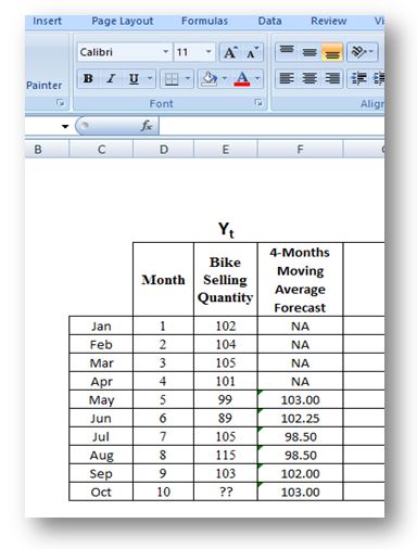
Let’s use a simple example, suppose a company would like to use a 3-month, 5-month, and 7-month simple moving average for forecasting sales of the company. The actual sales of the last 11 months are given below;

Calculate the Forecast value of December by using a 3-month, 5-month, and 7-month simple moving average method. i.e.

  • F=?, (Use 3-month SMA method)
  • F =?, (Use 5-month SMA method)
  • F =?, (Use 7-month SMA method)
MonthSales in Million Dollar ($M)
January150
February162
March155
April165
May170
June172
July164
August173
September168
October174
November169
December???
Answer:
SMA

Where, F = Forecast for the upcoming period.

n = Number of periods to be averaged.

 At-1, At-2, At-3 =Actual demands or occurrence in the past period up to “n” periods.

Forecast for December using the 3-month SMA method:

= (169 + 174 + 168)/3

= 170.33

Note: we have calculated the average of the past three month’s sales i.e. sales of November, October, and September.

The past 5-month sales values from July to November are 164, 173, 168, 174 & 169 (See the above table).

Forecast for December using a 5-month simple moving average method:

= (164 + 173 + 168 + 174 + 169)/5

                     = 169.6

Forecast for December using the 7-month SMA method (May to November):

= (170 + 172 + 164 + 173 + 168 + 174 + 169)/7

= 170

Forecast Table:

MonthSales in Million Dollar ($M)3-month SMA5-month SMA7-month SMA
January150   
February162   
March155   
April165   
May170   
June172   
July164   
August173   
September168   
October174   
November169   
December???170.33169.6170
How to calculate different types of SMA errors?

Here, we are going to calculate the main three types of Error i.e. [1] Mean Absolute Deviation (MAD). [2] (MSE) Mean Squared Error. [3] Mean Absolute Percent Error (MAPE). Suppose a company wants to use the 3-month simple moving average method to calculate the forecast value of sales and errors of each month w.r.t actual value. Month-wise sales are given below;

MonthSales quantity (Nos.)
April3000
May3500
June3300
July3400
August3450
September3501
October??

 By using a 3-month SMA method, we have calculated the forecast sales quantity from July to October as mentioned in the below table.

MonthSales quantity (Nos.)3-month SMA Forecast
April3000 
May3500 
June3300 
July34003266.67
August34503400
September35013383.33
October??3450.33

Now, we have to calculate the Error from July to September simply by subtracting the 3-month SMA forecast value from the Actual sales quantity.

Error of July = 3400 – 3266.67

= 133.33

August error value = 50

September error value = 117.67

There is no negative error value, so no need to calculate the absolute value, else calculate the absolute value.

Mean Absolute Deviation (MAD) = (133.33 + 50 + 117.67) / 3

= 100.33

Mean Squared Error (MSE) = (133.33²+ 50² + 117.67²) / 3

= (17776.89 + 2500 + 13846.22) /3

=11374.37

Absolute percent error of July = (133.33/3400) X 100

= 3.92

Absolute percent error of August = (50 /3450) X 100

= 1.45

Absolute percent error of September = (117.67 /3501) X 100

= 3.36

Mean Absolute Percent Error (MAPE) = (3.92 + 1.45 + 3.36) / 3

= 2.91%

How to calculate an SMA forecast in an Excel sheet using a data analysis option?

We have taken the same data table that was already considered for example and also we will cross-check the forecast value of both the methods (manual and Excel data analysis) by using a 3-month simple moving average.

Step-1: Open the Excel sheet and then follow the below options as;

  • Click on the “Data” option in the Excel sheet.
  • Enter on the “Data Analysis” option.
  • Select the “Moving Average “ option.
Simple Moving Average Formula

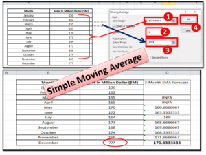
Step-2: After click on the “Data Analysis” option, a pop-up will appear on the screen. Now, you have to select the input range and enter the interval value. The details process is clearly mentioned in the below figure.

Simple Moving Average Formula

Now, as you can see the 3-month SMA forecast value of both the method is same and that is 170.33

How to calculate Moving Average forecast in an excel sheet using function option?

Step-1: First of all go through the data table given in below image. and based no the below data we are going to calculate the forecast value using 5-month simple moving average in excel sheet by applying function option, for doing so, you have to select the cell first, then apply the “Average’ function on that cell.

sma calculation

Step-2: Drag the “already applied average function cell” in the bottom right corner down to move the function formula to all cell.

sma calculation

Free Templates / Formats of QM: we have published some free templates or formats related to Quality Management with manufacturing / industrial practical examples for better understanding and learning. if you have not yet read these free template articles/posts then, you could visit our “Template/Format” section. Thanks for reading…keep visiting techiequality.com
Popular Post:

Gage R and R |Attribute type MSA |How to do MSA Study | Acceptance Criteria

Gage R and R

Gage R and R |Attribute type MSA |How to do MSA Study | Acceptance Criteria:

Hi readers! Today we will be discussing here on Measurement System Analysis. Basically on variable (Gage R and R) and attribute type MSA, how to do both MSA studies, and finally on the interpretation of result with manufacturing example.

Measurement System Analysis (Variable type MSA):

MSA is nothing but it’s a Measurement System Analysis. And also it is one of the AIAG core tools. As you know how important the process data that you are measuring, monitoring, and collecting for analysis. If unfortunately, those data may be wrong due to instrument error or human (appraisal) error then your whole analysis and decision will be incorrect. Some people think that we are doing calibration of our instrument, so why will we do the Variable MSA of the instrument?

Hence I’m trying to illustrate why it is required, suppose you are measuring the length of a product and during an inspection of the product inadvertently the vernier caliper has fallen on the ground and you used it in next time because you know your vernier caliper is calibrated and within the period. However, the condition of the instrument and instrument error may have varied after this incident happened. So we should analyze the gage repeatability and reproducibility of the instrument and need to make the decision accordingly. Similarly, in dusty and high moisture environments your instrument’s reading may be incorrect (more instrument error) due to bad conditions. So it is very important to do the variable type MSA on a periodic basis considering various factors, customer requirements, and standard requirements, etc.   

Attribute type MSA:

Similarly, we have to give attention to those who are doing inspection because the report of the inspection may be incorrect due to human error. For example, an inspector was doing a visual inspection of the colour box. And he accepted the lot of boxes and allowed to next process for operation. But the line manager has rejected the box due to a mismatch in the colour w.r.t approved master sample. When a quality manager tried to find out the cause of the incident later, he came to know that the person involved in the visual inspection was colour-blind. So it’s clearly indicating that the performance of the inspector was very low and miss-alarm & false-alarm was very high. Hence to prevent such types of mistakes we should periodically do the Attribute type of analysis to know the performance level of appraisal. A detailed interpretation is given below.

Below are some factors that may cause human error but these are not limited;
  • Vision problem
  • By following the wrong methods.
  • Insufficient knowledge.
How to do the Variable type MSA (Gauge repeatability & reproducibility)?

Step -1: First of all prepare the master calendar of MSA considering all instruments.

Step-2: List out the names of appraisers.

Step 3: E.g.- Every individual appraiser should measure the 10 samples with 3 trials, so in total there will be 30 measurements of individuals and 90 measurements of three appraisers.

Step-4: Calculate the % Gage R&R and “ndc” (No of distinct categories).

How to do the attribute type MSA?

Step-1: E.g.-Need to have 50 references and at least 10 bad parts. (At least 20 to 30 % of total reference-general practics).

Step-2: e.g.-Do a study and record the data of 50 parts with 3 trials in individuals of three appraisers.

Step-3: Calculate the % of Effectiveness, Miss-alarm, and false alarm of all three appraisers.

Interpretation of result:

Both the type of MSA result needs to be evaluated to determine, whether the measurement device is accepted or not. The acceptability criteria may depend on several factors but the general guidelines of acceptance criteria of both MSA (Variable and Attribute type) are given below.

General Acceptance Criteria of Gage R and R (Variable type MSA):
  • Generally, the measurement device to be acceptable when GR&R will be < 10% or NDC (Number of distinct categories) ≥ 5.
  • May be acceptable for some applications when Gage R&R will be 10% to 30%, during the decision making you should consider factors like the importance of application measurement, cost of rework, repair, and cost of the measurement device. But you should take approval from your customer as well.
  • The measurement device to be unacceptable when the GRR will be >30%.
General Acceptance Criteria of Attribute type MSA:
  • The decision to be an acceptable for the appraiser when Effectiveness ≥90% & Miss alarm ≤2% & False alarm ≤5%.
  • Marginally acceptable for the appraiser when Effectiveness ≥80% & Miss alarm ≤5% & False alarm ≤10%.
  • Unacceptable for the appraiser when Effectiveness <80% & Miss alarm >5% & False alarm >10%.
  • If you are considering the Kappa value to make a decision then, value >0.75 indicate good to excellent agreement.

Note: the above criteria are the general guideline for acceptability but you may consider the other factors during decision-making, for example, measurement system environment, Purpose, application, Cost of the measurement device, Cost of rework, cost of repair, total variation, etc.

Free Templates / Formats of QM: we have published some free templates or formats related to Quality Management with manufacturing / industrial practical examples for better understanding and learning. if you have not yet read these free template articles/posts then, you could visit our “Template/Format” section. Thanks for reading…keep visiting techiequality.com
Useful Post:

How to do data analysis by excel sheet? Step by step guides

Types of Fishbone Diagram |Dispersion Analysis |Enumeration |Process Classification

Dispersion Analysis Cause & Effect Diagram Template |Download Excel Format

Strategies for Manufacturing Process Improvement |11+ Strategies

More on TECHIEQUALITY

Popular Post:

Correlation analysis in excel |3 best method |step by step guide with example

Correlation analysis in excel

Correlation analysis in excel | 3 best method |step by step guide with example

Hi reader! Today we will discuss on Correlation analysis in excel, this tool is generally used to know the correlation between two variables. There is so many software available in the market that you can execute the correlation test. But in this tutorial, we will explain to you how to do a correlation test in excel with an industrial example. There are three common methods that you can execute for the test i.e. [1] shortcut function method [2] direct function method [3] Through data analysis method. For doing the data analysis method you have to install the analysis tool pack if you have not yet installed then follow the steps to install it. The Link is given below.

Step by step guide for installation of Data Analysis tools in excel.

Processes of Correlation analysis in excel:

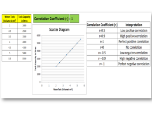
There are three common methods that we are going to explain it step by step. Here we have analyzed the correlation between variables “water tank (volume) vs Tank capacity” to know the interpretation of correlation and value of the coefficient of correlation. A Data table is given below;

Water Tank (Volume in m3) Tank Capacity in liters’
2 2000
2.5 2500
3.5 3500
4 4000
4.3 4300
5 5000
5.5 5500

Method -1;

Step-1:

Open the Excel sheet, then create a table of two variables, and next, click on the function button. Follow the below figure.

Correlation analysis in excel

Step-2:

After clicking on the function button, the below interface will appear.

Correlation analysis in excel

Step-3:

Type “correlation” on the search bar and search the function, then select the function “CORREL”.

step by step guide of correction analysis

Step-4:

Select the data for array1 and array2; here we have selected the column of water tank volume as array1 and tank capacity as array2.

Correlation analysis in excel
Example

Step-5:

The Correlation coefficient will be calculated automatically. You can see in the below figure the value of the coefficient of correlation is 1. For better understanding, we have plotted the scatter diagram. And the graph and value of the coefficient of correlation indicate that there is a perfect positive correlation between the two variables.

Correlation analysis in excel

Method-2;

Step-1:

Select the correlation function from the statistical option, and go through the below figure.

Example

Step-2:

Select the data for array1 and array2 from the data table.

Example

Step-3:

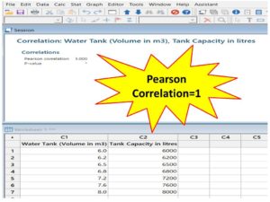
The Value of the coefficient of correlation will be calculated automatically.

Correlation analysis in excel

Method-3;

Step-1:

Ensure that the data analysis tool has been installed already in Excel, else click here to learn the step-by-step process. Now go to the data option and select the data analysis option.

Example

Step-2:

Select the input data range

example-1

Step-3:

The Correlation coefficient will be calculated automatically.

Correlation analysis in excel

Interpretation of Correlation coefficient (r):

Correlation Coefficient (r ) Interpretation
r=0.5 Low positive correlation
r=0.9 High positive correlation
r=1 Perfect positive correlation
r=0 No correlation
r= -0.5 Low negative correlation
r= -0.9 High negative correlation
r= -1 Perfect negative correlation

Similar Post:

How to Plot Scatter Diagram in Excel? |Guides with example | Interpretation.

Scatter Diagram Template |Industrial Example |Download Excel Format.

Free Templates / Formats of QM: we have published some free templates or formats related to Quality Management with manufacturing / industrial practical examples for better understanding and learning. if you have not yet read these free template articles/posts then, you could visit our “Template/Format” section. Thanks for reading…keep visiting techiequality.com
More on Techiequality